| Owner | SAPCO | |
|
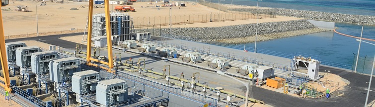
Shuweihat S3 IPP 2 x SCC5-4000F(6) 2+1 (Drum) |
|
| Owner's Engineer | Fichtner | |
| Consortium | Siemens AG & DAEWOO E&C | |
General Description
The Consortium of
Daewoo E&C and Siemens AG, Energy Sector Fossil Power Generation Division,
has been selected as the potential EPC Contractor by a consortium led by
Sumitomo Corporation and Korea Electric Power Corporation and thereafter has
been duly awarded by SAPCO (between Sumitomo, KEPCO and ADWEA(now TAQA)) the contract
for the turnkey installation of the CCPP Shuweihat S3 in Abu Dhabi - UAE.
The Power Plant will have a rated net electrical output of approx. 1600 MW at RSC.
The Power Plant will be equipped with two blocks, each with two (2) SGT5-4000F(6), two (2) dual pressure Heat Recovery Steam Generators (HRSG) with bypass stack (only unit 80) and supplementary firing, and one (1) Steam Turbine SST5-4000, 2x12,5 m2.
The Power Plant will be suitable for base load and intermittent part load operation. The GTs are fired with natural gas or with distillate oil as a back-up fuel, supplementary firing for the HRSGs is designed for natural gas only.
The HRSGs are designed as dual pressure drum type HRSGs with condensate preheating. The evaporators are designed as natural circulation evaporators.
The ST (SST5-4000, 2x12,5 m2) is a dual-casing condensing turbine. The turbine exhaust steam is condensed in two split, two-pass condensers, arranged at both sides of the LP turbine. The condensers will be cooled by seawater.
Description of Main Components and Systems
Gas Turbine
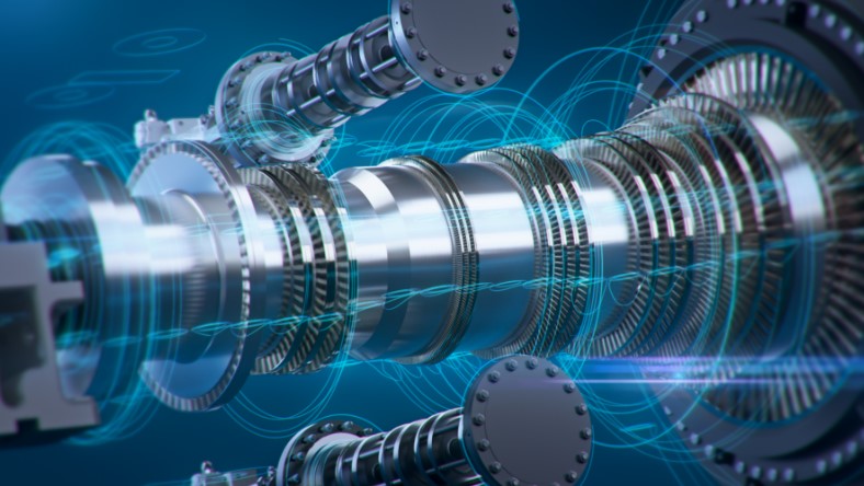
The SGT5-4000F(6) GT consist essentially of a multiple-stage axial compressor, an annular combustion chamber with 24 hybrid burners for gas and oil firing and a multiple-stage axial turbine.
The compressor takes ambient air through an inlet air filter, compresses it and feeds it to the combustion chamber. The fuel is fed into the combustion chambers and is burned with the compressed air. The resulting hot, compressed combustion gas flows from the combustion chambers into the turbine.
|
|
Heat Recovery Steam Generator (HRSG)
The HRSGs are horizontal dual pressure HRSGs with natural circulation evaporator systems.
A condensate preheater heats the entire condensate flow approximately to boiling temperature of the LP system. Downstream of the condensate preheater the condensate flow is split to LP and HP/IP stage respectively bypass deaerator. The LP feedwater goes directly from the condensate preheater to the LP drum. From the drum, water is fed into the natural circulation evaporator. The resulting water steam mixture returns to the drum, where it is separated by separators. The separated saturated steam is fed to the superheater and is heated further to LP steam temperature.
The HP feedwater goes from the condensate preheater to the feedwater pumps (3x50% for 2 HRSGs). The HP systems of the HRSGs consist of economizers, evaporator, drum and superheaters.
The HP feedwater is heated approximately to boiling temperature in the economizers and fed to the drum. Through the down comers water flows geodetically from the drum to the evaporator, where a portion is evaporated. Due to density differences the resulting water/steam mixture returns to the drum and is separated by separators. The arising water is remaining in the drum and the separated, saturated steam is fed to the superheater section and is heated further to main steam temperature.
During combined cycle operation the generated HP steam of both HRSGs is fed to the HP part of the steam turbine by a common HP main steam line and is expanded to low pressure.
The generated low pressure steam is fed to the connection of the LP-steam supply towards the LP section of the ST and the entire steam flow is completely expanded to condenser pressure in the LP section of the ST.
During ST start-up or high ambient temperature operation the HP main steam temperature is controlled to the requirements of the ST by one interstage and one final stage attemporator. The condensate preheater inlet temperature is kept above 96°C/113°C (setpoint depending on sulfur content in fuel gas) for gas operation due to the sulphuric acid dew point.
For oil operation, a condensate preheater inlet temperature of 124/140°C (setpoint depending on sulfur content in fuel oil) is specified to avoid corrosion on the flue gas side due to the sulphuric acid dew point. The necessary CPH inlet temperature is achieved by a sequence of control measures. First circulating hot condensate from an extraction line of the feedwater pump to the condensate preheater inlet is activated. In addition two condensate recirculation pumps are taken in service. By means of higher condensate recirculation mass flow and partly condensate bypassing the CPH the condensate preheater inlet temperature is increased. The condensate preheater inlet and outlet temperatures are thus controlled by means of bypass line and condensate recirculation.
As the exhaust heat input into the condensate preheater is not always sufficient without additional measures a certain amount of feedwater is bypassed around the HP economizer. Thereupon the inlet temperatures into the HP drum is lowered and the HP steam production decreases. Therefore more exhaust heat is available to the LP stage. To reduce steam production in the LP stage the LP pressure is increased and in consequence due to reduced LP steam production more exhaust heat is available to the condensate preheater.
As a final measure condensate can be bypassed around the CPH to reduce the CPH flow thus increasing the CPH inlet temperature.
During oil operation the bypass deaerator will be used as additional mixing preheater in order to achieve a minimum economizer inlet temperature of approx. 140°C.
Both HRSGs share one common installation for feedwater and condensate recirculation and for condensate bypass.
During operation of the bypass deaerator, the deaerator inlet temperature is controlled by means of the cold bypass to approximately 8K below deaerator temperature to allow sufficient deaeration. For plant power augmentation a burner grid is located in the HRSG inlet duct upstream of the heating surfaces.
Steam Turbine
The SST5-4000 is a dual-casing condensing turbine with a HP turbine section (D type) and a double flow LP turbine (N type) with 2x12,5 m2.
The HP main steam of the HRSGs flows to the HP turbine section. The exhausted HP steam is fed into the LP turbine inlet and combines with inducted LP steam produced by the HRSG LP system.
This combined steam flow is expanded in the LP turbine section. The exhaust steam of the LP turbine flows radially out of the steam turbine to the condenser. The HP section of the turbine is operated in sliding pressure mode from 100 - 60% ST output and in fixed pressure mode below this load range in case both HRSGs are in operation.
The LP section steam system is operated in fixed pressure over the whole entire load range. The ST drives its related generator.
During HRSG start-up and shutdown and in ST bypass operation, high pressure and low pressure steam are fed directly (cooled by injection water) to the condenser via the HP and LP bypass stations. Cooling water pumps ensure the cooling water circulation through the condenser directly cooled by seawater. The ST drives the related generator. During combined cycle operation, with both GT/HRSG sets in operation, HP main steam pressure is controlled by the ST inlet control according to the natural sliding pressure characteristic between 100% and 60% main steam pressure related to 100% to 60% steam mass flow. Below 60% mass flow the pressure is limited to fixed pressure level, means 60% of rated pressure. In case only one GT/HRSG is in operation, the HP sections are operated with "equivalent" sliding pressure: The 1+1 (1 GT/HRSG + 1 ST) operating pressure is equivalent to 2+1 operating pressure at equal steam mass flow per HRSG, as well down to fixed pressure.
The condenser pressure is resulting from the arising amount of steam and from cooling system design and cooling water temperature. During ST start-up the main steam temperature setpoint for an optimized ST start-up is given by the ST control logic to the unit coordination control respectively main steam temperature control.
Water-Steam Cycle
The water-steam cycle consists primarily of the condensate system, feedwater system and steam system. The condensate is extracted from the condenser hotwell and delivered to the CPHs via condensate extraction pumps. The condensate is preheated in the preheaters of the HRSGs and transferred to the LP drum respectively to the bypass deaerator and feedwater pumps.
The feedwater system supplies the volume of water to the HP sections of the HRSGs which is discharged as MS or steam generator blowdown. The make-up and feedwater quality shall be according to VGB guidelines for boiler feedwater, boiler water and steam of steam generators with a permissible operating pressure >68 bar ("VGB-R450Le").
The HP and LP steam generated in the HRSGs is fed via the steam systems to the steam turbine in the turbine building. Before and during plant start-up the bypass deaerator can be heated using auxiliary steam taken from the auxiliary steam system to shorten the start-up procedure. The auxiliary steam system additionally supplies auxiliary steam to the ST for sealing purpose. For start-up, shutdown and 1+1 operation each HRSG can be disconnected by shutoff valves.
Cooling Systems
The turbine exhaust steam is condensed in a divided, two-pass condenser. Each of the two condenser shells is arranged laterally at the double side exhausting LP Turbine. Each condenser shell is cooled with seawater once through cooling by means of circulating water pumps.
Two different service cooling water systems are provided to supply cooling water to each closed cooling water heat exchanger (plate type). One service cooling water system is used to perform cooling of the GT and ST generators, GT and ST components and water steam components coolers. For this system a second heat exchanger (plate & frame type) is provided as back-up.
The service cooling water system for this part supplies the closed cooling water heat exchanger with cooling water taken from the sea by means of 2x100% booster pumps.
The second service cooling water system is used to perform cooling of the compressed gas in case the gas compressors are in operation. A second heat exchanger (plate & frame type) as stand-by is also provided for this system. This common cooling water circuit can be fed with service cooling water by both groups from the sea by means of 2x100% booster pumps.
In order to maintain a seawater temperature rise ≤ 5°C the outlet of the ST condenser and the heated service cooling water return line will be mixed with seawater from the seawater-intake by means of a quenching pump.
The dedicated closed cooling water systems supply cooling water by means of 3x50% pumps - assigned to each closed cycle - to the connected component coolers, mainly the W/S cycle pumps, GT and ST component and generator coolers, whereas the second closed cooling water system supplies cooling water to the gas compressor cooler.
Turbine Generators
The generators for the GTs are air cooled types (SGen5-1000A, TLRI 118/55), the generators for the STs are hydrogen cooled types (SGen5-2000H, THRI 110/55).